 PDF(578 KB)

A New Design of Electrical Impedance Tomography Sensor System for Pulmonary Disease Diagnosis
Xiaoyuan LIU, Shihong YUE, Zeying WANG
Journal of Systems Science and Information ›› 2018, Vol. 6 ›› Issue (5) : 473-480.
PDF(578 KB)
PDF(578 KB)
A New Design of Electrical Impedance Tomography Sensor System for Pulmonary Disease Diagnosis
As an advanced process detection technology, electrical impedance tomography (EIT) has wide application prospects and advantages in medical imaging diagnosis. However, a series of issues need to be addressed before applying EIT for bedside monitoring. Medical diagnosis and bedside monitoring are dynamic measuring process, where the positions of measuring electrodes and the shape of the detected field are changing dynamical. Due to the inability to cope with the changeable electrode positions and various dynamic fields, existing EIT systems are mainly used for industrial detection in condition of static measurement and visualization. In this paper, we investigate the dynamic measurement and visualization of human breast in EIT field, describe the design of the measuring sensor system, and expound the measuring principle. The main component of the hardware system is a builtin servo electrical resistance tomography sensor with capacitive sliding rod, which can adapt to the crowd of different chest contour and the change of chest shape in the dynamic process of breathing. The corresponding measuring principle is extracting all real-time positions of measuring electrodes, then obtaining the dynamic boundary, finally dividing the detection field rapidly. Experimental results confirmed that the proposed system can obtain real-time location of boundary sensor and dynamically solve the problem of arbitrary-shape boundary measurement. The imaging results validate the availability of designed sensor system and the effectiveness of the corresponding measuring principle.
electrical impedance tomography / non-invasive / dynamic boundary / human breast / sensor {{custom_keyword}} /
| 1 |
{{custom_citation.content}}
{{custom_citation.annotation}}
|
| 2 |
{{custom_citation.content}}
{{custom_citation.annotation}}
|
| 3 |
{{custom_citation.content}}
{{custom_citation.annotation}}
|
| 4 |
{{custom_citation.content}}
{{custom_citation.annotation}}
|
| 5 |
{{custom_citation.content}}
{{custom_citation.annotation}}
|
| 6 |
{{custom_citation.content}}
{{custom_citation.annotation}}
|
| 7 |
{{custom_citation.content}}
{{custom_citation.annotation}}
|
| 8 |
{{custom_citation.content}}
{{custom_citation.annotation}}
|
| 9 |
{{custom_citation.content}}
{{custom_citation.annotation}}
|
| 10 |
{{custom_citation.content}}
{{custom_citation.annotation}}
|
| 11 |
{{custom_citation.content}}
{{custom_citation.annotation}}
|
| 12 |
{{custom_citation.content}}
{{custom_citation.annotation}}
|
| 13 |
{{custom_citation.content}}
{{custom_citation.annotation}}
|
| 14 |
{{custom_citation.content}}
{{custom_citation.annotation}}
|
| 15 |
{{custom_citation.content}}
{{custom_citation.annotation}}
|
| {{custom_ref.label}} |
{{custom_citation.content}}
{{custom_citation.annotation}}
|
The authors gratefully acknowledge the editor and referees for their insightful comments and helpful suggestions that led to a marked improvement of the article.
PDF(578 KB)
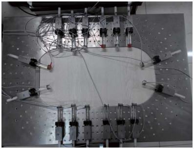
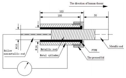
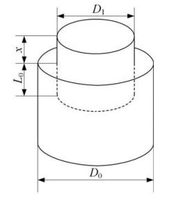
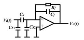
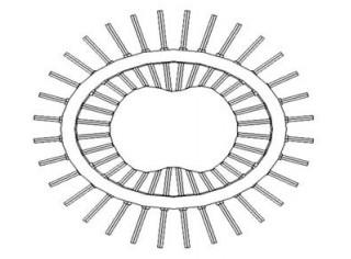
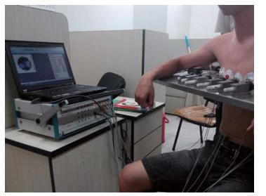
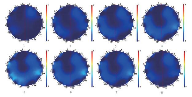
 Figure 1 Manufactured sensor systemFigure 2 The structure of the new sensorFigure 3 Concentric cylindrical capacitance sensorFigure 4 C/V converting circuitFigure 5 The chest boundary diagramFigure 6 A real-time measurement to a volunteerFigure 7 A real-time measurement to a volunteer
/
| 〈 |
|
〉 |


